Home/Mechanical/Suspension system design
Suspension system design
MECH4002 group project, technical lead · ANSYS Workbench, SolidWorks · 2025
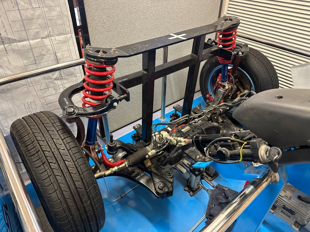
This group project took a car's front suspension from a real rig to FEA. The supplied drawings were thin, so we measured the rig by hand, modelled it in SolidWorks, ran static, modal and transient analysis in ANSYS Workbench, and redesigned it once from the stress plots. There were three of us. We shared the CAD modelling at the start, then I ran the FEA and the redesign.
Getting the model to move
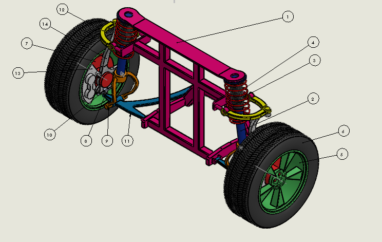
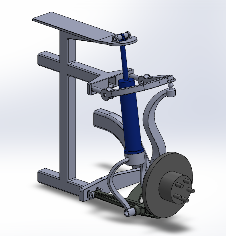
The first assembly was 14 parts and couldn't articulate, because the strut was one rigid body. The strut became a two-part sliding pair, the bushes became ball joints that could drop in wherever rotation was needed, and the coil spring became a virtual spring in ANSYS, about 29 N/mm, so rate and preload could change without going back to CAD. Halved on its plane of symmetry, the model went to analysis as nine parts.
First results
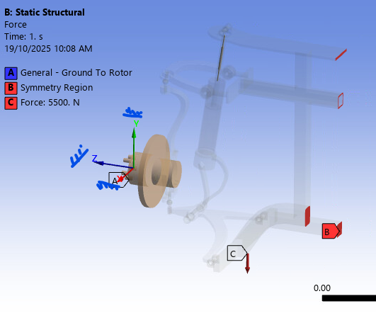
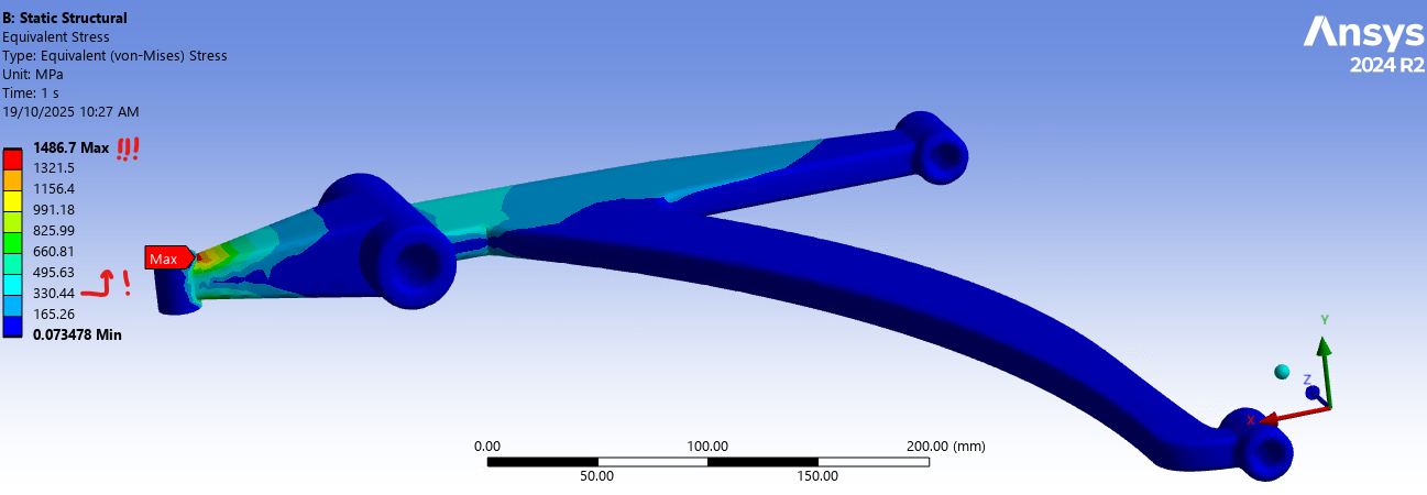
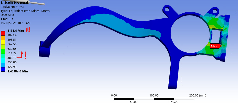
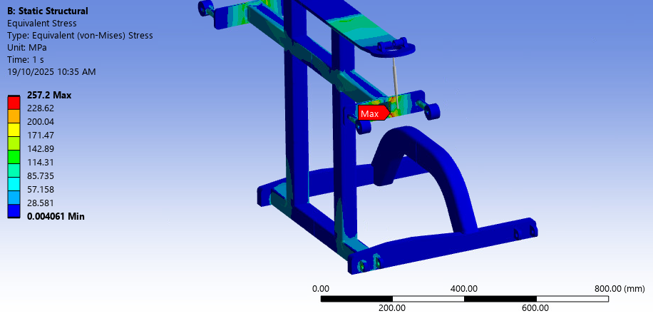
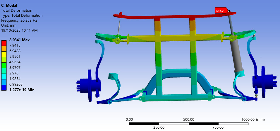
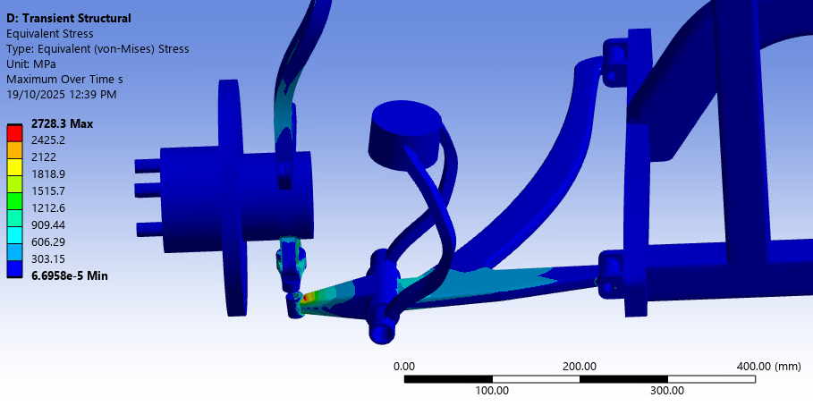
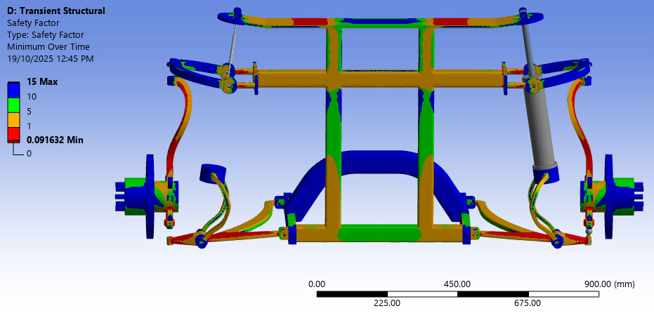
Getting it to solve took joints wherever there was a degree of freedom and bonded contacts between faces, after either alone had failed. A mesh study settled on 10 mm elements. The first stresses were far over yield at the joint transitions, the speed-bump case roughly doubled them, and the first 10 modes sat inside the road-noise band.
The redesign
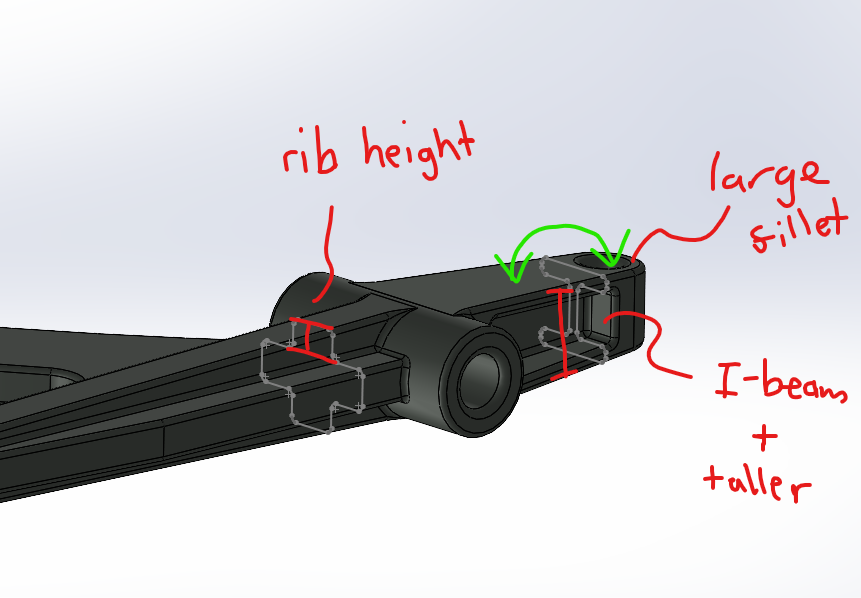
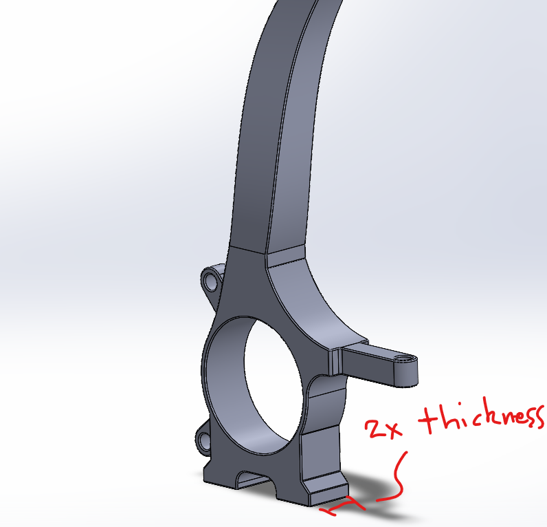
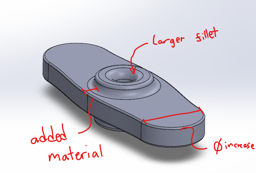
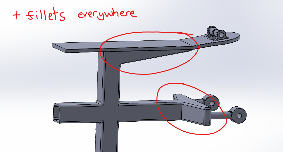
There was time for one round, aimed at bending: fillets, thicker sections and an I-beam lower control arm, each sized to raise the section's second moment of area. That gave a predicted stress at every hot spot before the FEA was re-run. Every location came down, most by 70% or more. The FEA results sit above the predictions because what was left was mostly shear and contact stress at the joints, which a bending estimate doesn't include.
- Lower arm, knuckle end
- 1,487 → 365 MPa, down 75% (predicted 232)
- Lower arm, mid-span
- 496 → 110 MPa, down 78% (predicted 72)
- Knuckle
- 1,151 → 321 MPa, down 72% (predicted 144)
- Lower knuckle
- 640 → 337 MPa, down 47% (predicted 103)
- Frame, strut mount
- 143 → 2.7 MPa, down 98% (predicted 2.4)
- Frame, upper arm mount
- 257 → 10.8 MPa, down 96% (predicted 2.7)
What I took from it
Running the analysis taught me not to trust the first contour plot. The stresses were high enough that we doubted the method before the design, and the one hot spot left after the redesign, inside the ball-joint holes, is most likely a contact singularity from a rigid body bonded to a deformable one. Next time I'd model the ball joints as part of each component to find out. The other lesson, which the report states plainly, is that CAD and FEA have to iterate, and that real control arms are high-strength steel for a reason.
- Message
- Send me a message
- in/jeremy-alec-osborne
- Based in
- Sydney, NSW