Home/Mechanical/Aerodynamic optimisation of a 150 m wind turbine
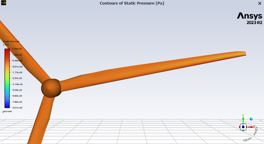
Aerodynamic optimisation of a 150 m wind turbine
Honours thesis, supervised by Dr Ming Zhao · ANSYS Fluent · 2025
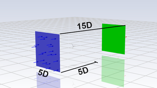
Wind farms space turbines 7 to 10 rotor diameters apart, because a turbine behind another one runs in its wake. My honours thesis asked how tightly they can be packed: how close a second turbine can sit before the lost power outweighs the extra density. For turbines inline, the answer is five diameters.
What went into it
- Blade
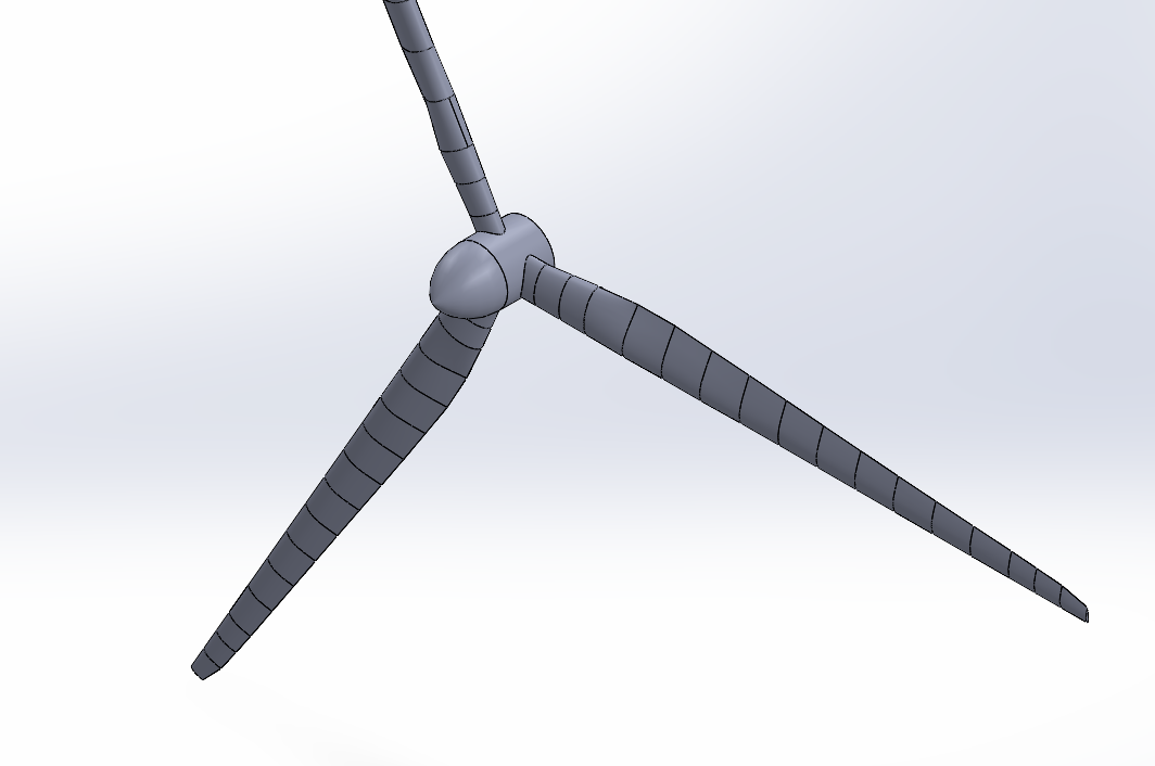
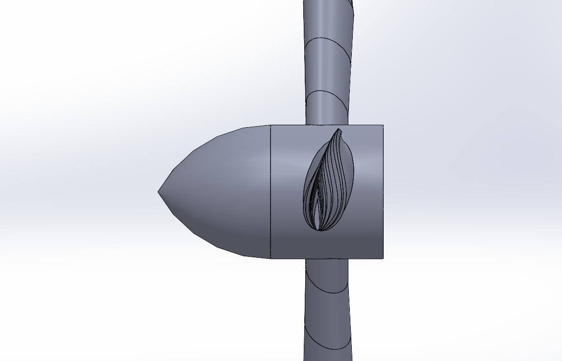
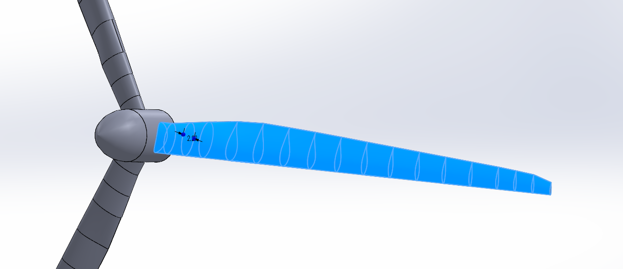
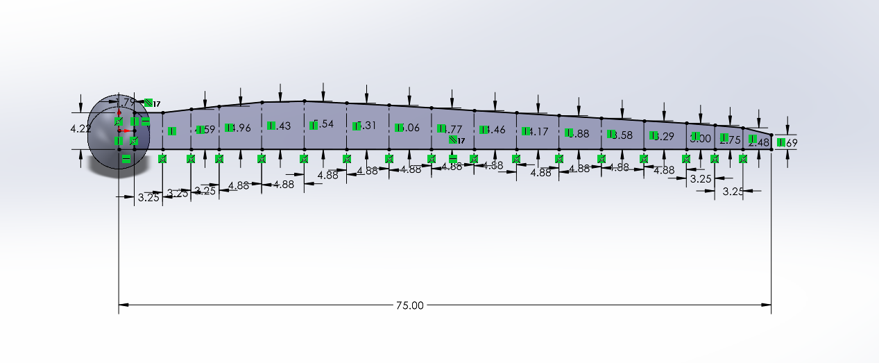
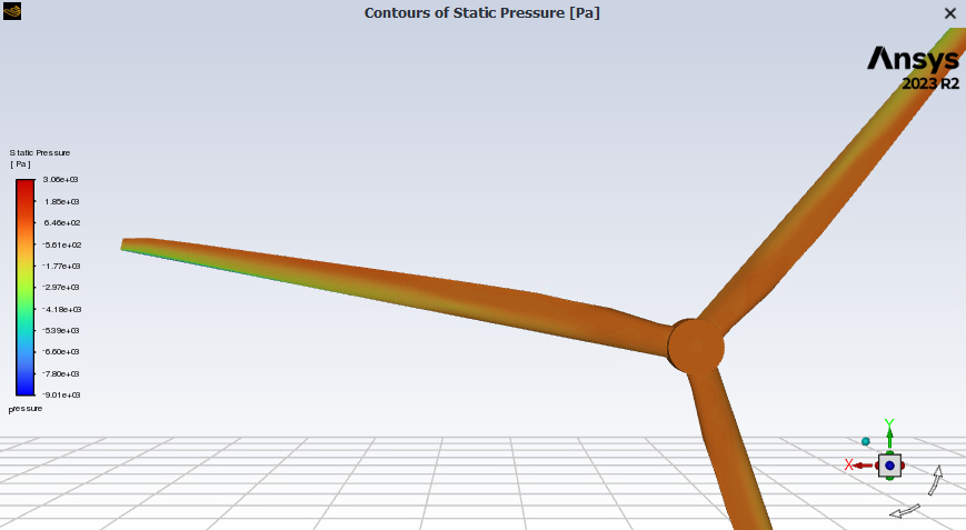
- A simple first blade to get reps in, then a twisted 150 m rotor scaled from the NREL 5 MW, with 67.6% more peak power
- Mesh
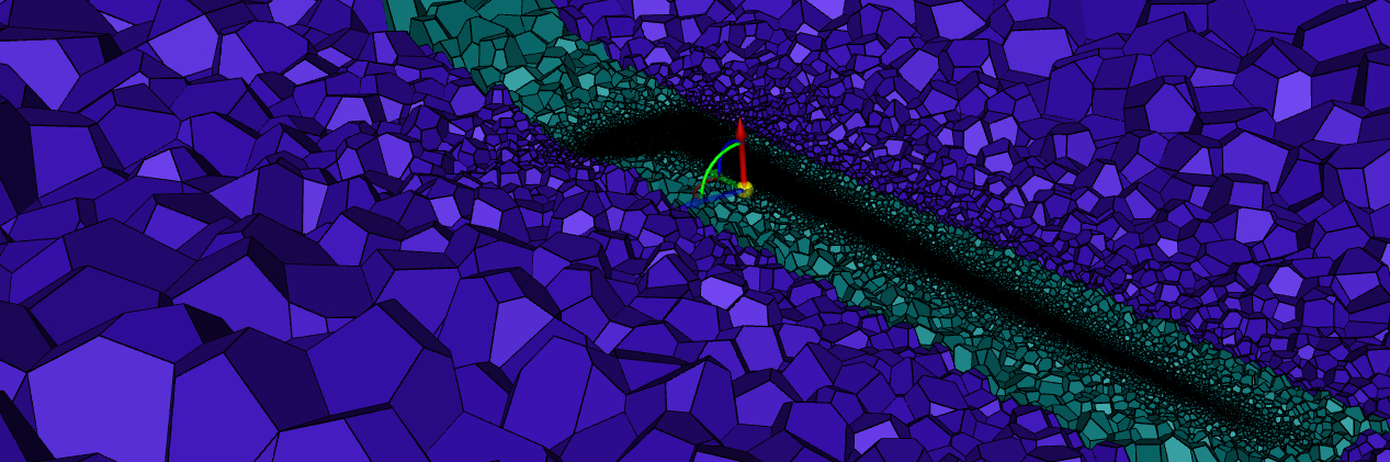
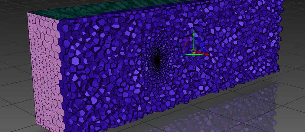
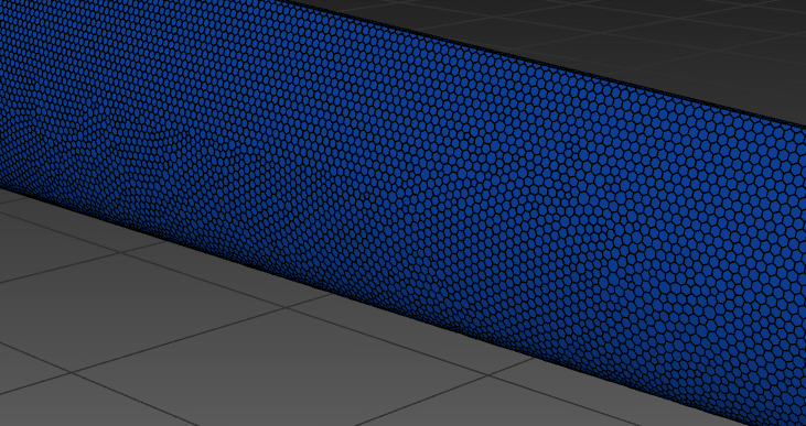
- Fluent Meshing with polyhedral cells, 6.65 million elements, after ANSYS Meshing failed on the twisted blade
- Solver
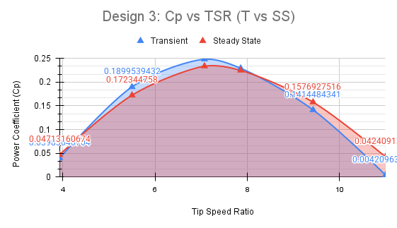
- Full-rotor transient CFD in ANSYS Fluent: 47 runs, 1,944 CPU hours. Steady state was tried to save time and dropped
- Second turbine
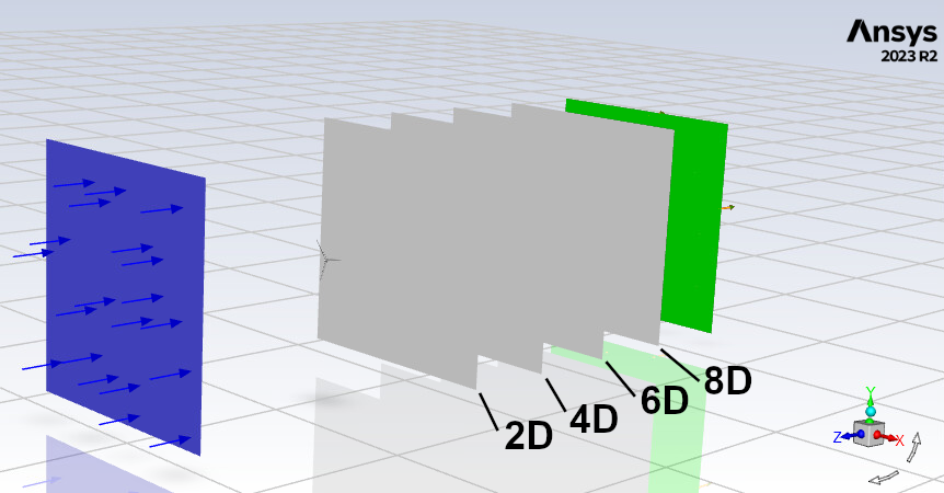
- Emulated from the first one's wake, when a true two-rotor model wouldn't fit the time left
The result
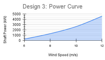
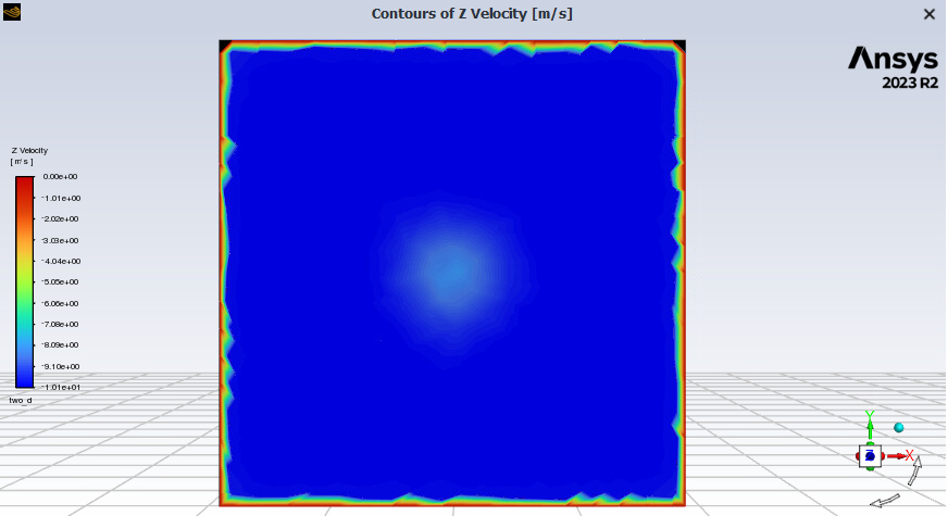
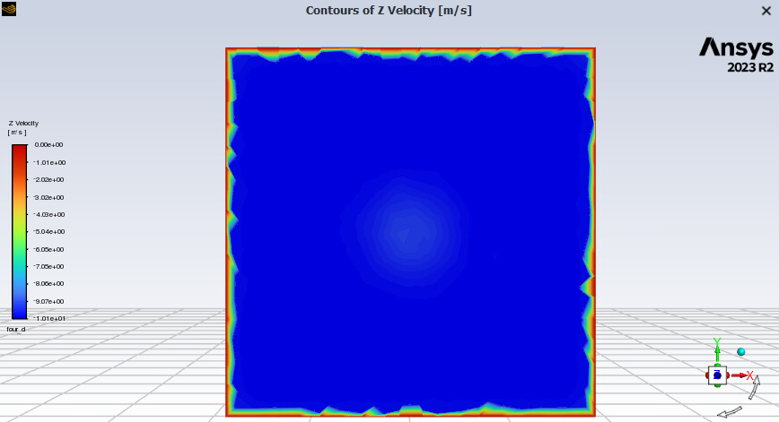
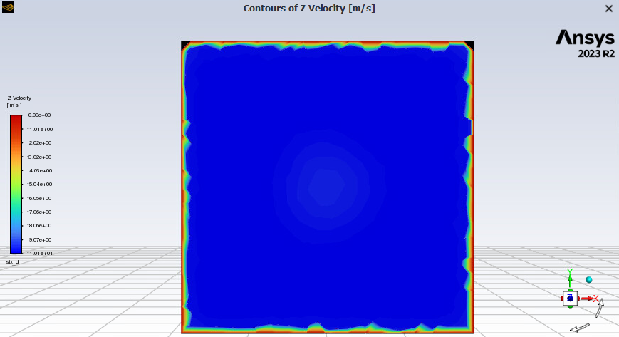
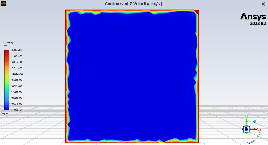
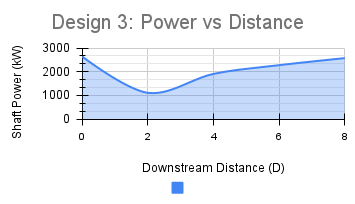
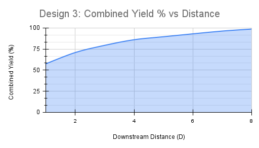
The second turbine made 1,106 kW two diameters back, rising to 2,572 at eight, against 2,640 in clean air. Eight diameters gets the pair to 98.7% combined yield against 89.6% at five, but a row spaced at five fits 60% more turbines into the same length. That's why five diameters is the recommendation for turbines inline.
What I took from it
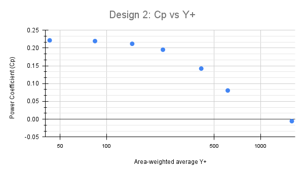
I started the year with coursework-level CFD and finished with 47 simulations and about 500 hours of my own time against a nominal 300. Most of what I learned was when to trust a number: a coarse mesh read high, steady state read low, and nothing meant anything until it had been checked. Next I'd run a true two-rotor model and test a staggered layout. The wake never gets wider than about 1.34 diameters, so offsetting the second turbine sideways should get close to full yield, but that's still an assumption.
- Message
- Send me a message
- in/jeremy-alec-osborne
- Based in
- Sydney, NSW